
Week - 6: Embedded Programming
During Week 6, we delve into the fascinating world of embedded programming. Embedded programming refers to the process of writing code for devices other than computers. These devices, known as embedded systems, are specialized computing devices that perform specific tasks. Examples include the electronic systems in cars, airplanes, home appliances, and more. This week, we will explore the fundamentals of embedded programming, learn about the different types of microcontrollers, and begin writing code for these systems. We will also discuss the unique challenges and considerations when programming for embedded systems.
Objectives for the week:
Individual assignment:
- Write a program for the microcontroller development board you made. The program should be able to interact with local input and/or output devices, and communicate with remote wired or wireless devices.
- Extra credit: Use different languages and/or development environments.
- Extra credit: Connect external components to the board.
Group assignment:
- Browse through the data sheet for your microcontroller.
- Compare the performance and development workflows for other architectures. Link
Here are the steps to write a program on Arduino IDE to blink the LED on pin 26 of the development board:
- Install the Arduino IDE: Download and install the Arduino Integrated Development Environment (IDE) on your computer.
- Open the Arduino IDE: Once installed, open the Arduino IDE.
- Create a New Sketch: In the Arduino IDE, go to "File" > "New" to create a new sketch. Using the board manager option, I selected my board as Seeed Xiao RP2040.
- Write the Code: Now, you will write the code for blinking the LED. The code will look something like this:
// Defines pin number
const int LED_PIN = 26;

// the setup function runs once when you press reset or power the board
void setup() {
  // initialize digital pin as an output.
  pinMode(LED_PIN, OUTPUT);
}

// the loop function runs over and over again forever
void loop() {
  digitalWrite(LED_PIN, HIGH);   // turn the LED on (HIGH is the voltage level)
  delay(1000);                   // wait for a second
  digitalWrite(LED_PIN, LOW);    // turn the LED off by making the voltage LOW
  delay(1000);                   // wait for a second
}
- Select the Board: Go to "Tools" > "Board" > and select the appropriate board from the list.
- Select the Port: Go to "Tools" > "Port" > and select the port where your Arduino board is connected.
- Upload the Code: Click the "Upload" button in the Arduino IDE to upload your code to the Arduino board. If everything is connected correctly, the LED on pin 26 of your board should start blinking.
There are various methods to define LED pins in Arduino programming, each with its own advantages.
One common method is using
#define
preprocessor directive. This replaces all instances of the defined identifier with the defined value before the code is compiled. It doesn't use any memory in the microcontroller, making it efficient for memory-critical applications.
#define LED_PIN 26
Another method is the use of
const int
. This declares a constant integer variable, which means the value cannot be changed after it's set. This method is type-safe and makes the code easier to read.
const int LED_PIN = 26;
You can also directly mention the pin number in your code. However, this method can make your code harder to read and maintain, especially for larger projects.
digitalWrite(26, HIGH);
These techniques are useful because they make your code more readable and maintainable. By defining the pin number at the start of your program, you can easily change the pin number if needed without having to go through your entire code.
After understanding how to blink a single LED, let's now write an Arduino program to blink three LEDs simultaneously with a push button on the SEEED Xiao RP2040 board. We'll use pins 0, 1, and 26 for the LEDs and pin 27 for the push button.
Here's the Arduino code to accomplish this:
// Define pin numbers
const int LED_PIN1 = 0;
const int LED_PIN2 = 1;
const int LED_PIN3 = 26;
const int BUTTON_PIN = 27;

// the setup function runs once when you press reset or power the board
void setup() {
  // initialize digital pins as outputs
  pinMode(LED_PIN1, OUTPUT);
  pinMode(LED_PIN2, OUTPUT);
  pinMode(LED_PIN3, OUTPUT);

  // initialize button pin as input
  pinMode(BUTTON_PIN, INPUT);
}

// the loop function runs over and over again forever
void loop() {
  int buttonState = digitalRead(BUTTON_PIN);

  // check if the pushbutton is pressed. If it is, the buttonState is HIGH
  if (buttonState == HIGH) {
    digitalWrite(LED_PIN1, HIGH);   // turn the LED on
    digitalWrite(LED_PIN2, HIGH);   // turn the LED on
    digitalWrite(LED_PIN3, HIGH);   // turn the LED on
    delay(1000);                    // wait for a second
    digitalWrite(LED_PIN1, LOW);    // turn the LED off
    digitalWrite(LED_PIN2, LOW);    // turn the LED off
    digitalWrite(LED_PIN3, LOW);    // turn the LED off
    delay(1000);                    // wait for a second
  } else {
    // if the pushbutton isn't pressed, turn off the LEDs
    digitalWrite(LED_PIN1, LOW);
    digitalWrite(LED_PIN2, LOW);
    digitalWrite(LED_PIN3, LOW);
  }
}
This program will continuously check the state of the button. When the button is pressed (HIGH state), it will turn on the LEDs, wait for a second, turn off the LEDs, and then wait for another second before repeating the cycle. If the button isn't pressed, it will keep the LEDs off.
Output
Here’s a program I explored for switching on the LEDs on pin 0, 1 and 26 are off when the push button is pressed and vice versa.
/*
  Button

  Turns on and off a light emitting diode(LED) connected to digital pin 0, 1 and 26,
  when pressing a pushbutton attached to pin 27.
  */
const int buttonPin = 27;  // the number of the pushbutton pin
const int ledPin = 1;      // the number of the LED pin
const int ledPin1 = 0;
const int ledPin2 = 26;
// variables will change:
int buttonState = 0;  // variable for reading the pushbutton status
bool flag = false;

void setup() {
  // initialize the LED pin as an output:
  pinMode(ledPin, OUTPUT);
  pinMode(ledPin1, OUTPUT);
  pinMode(ledPin2, OUTPUT);
  pinMode(buttonPin, INPUT);
}

void loop() {
  // read the state of the pushbutton value:
  buttonState = digitalRead(buttonPin);

  // check if the pushbutton is pressed. If it is, the buttonState is HIGH:
  if (buttonState == HIGH) {


    if (flag == true)

    {
      flag = false;
    } else {
      flag = true;
    }
  }


  if (flag == true)
  {  // turn LED on:
    digitalWrite(ledPin, HIGH);
    digitalWrite(ledPin1, HIGH);
    digitalWrite(ledPin2, HIGH);
  }
  else {
    // turn LED off:
    digitalWrite(ledPin, LOW);
    digitalWrite(ledPin1, LOW);
    digitalWrite(ledPin2, LOW);
  }
}
Output
Our instructor helped us to develop algorithms to understand the underlying steps followed by the code.
He shared an algorithm with us for the first blink program as follows:
LED blink algorithm
Step1:- set pin 26 as Output for LED 1
Step2:- set LED1 On
Step3:- 1 second delay
Step4:- set LED1 Off
Step5:- 1 second delay
Step6:- go to step 2
Using this example, I developed the algorithm for the button program for toggling on and off the LED as follows:
Step 1: Set pin 27 as input pin for the tactile push button
Step 2: Set pins 0, 1, and 26 as outputs for LEDs.
Step 3: LED on when push button is pressed and go to step 5
Step 4: LED off.
Step 5: Go to step 3.
Using this example, I developed the algorithm for the button program as follows:
Step 1: Set pin 27 as input pin for the tactile push button and set pins 0, 1, and 26 as outputs for LEDs.
Step 2: If button is pressed, LED ON
Step 3: Update the flag to true only if the LED is ON.
Step 4: If the flag is true when button is pressed, LED OFF.
Step 5: Go to step 2.
Alternate:
Step 1: Set pin 27 as input pin for the tactile push button and set pins 0, 1, and 26 as outputs for LEDs.
Step 2: If button is pressed, LED ON
Step 3: If LED ON, turn off LED when button is pressed again
Step 4: Go to step 2.
We were asked to write our own program using the above algorithm and the program I wrote is as follows:
// Define the pin numbers
const int buttonPin = 27;
const int ledPin1 = 0;
const int ledPin2 = 1;
const int ledPin3 = 26;
bool ledState = false; // false means LEDs are OFF, true means LEDs are ON
bool buttonState = false;
bool pressed = false;
void setup() {
  // Initialize the button pin as an input with an internal pull-up resistor
  pinMode(buttonPin, INPUT);

  // Initialize the LED pins as outputs
  {
    pinMode(ledPin1, OUTPUT);
    digitalWrite(ledPin1, LOW);
    pinMode(ledPin2, OUTPUT);
    digitalWrite(ledPin1, LOW);
    pinMode(ledPin3, OUTPUT);
    digitalWrite(ledPin3, LOW);// Make sure LEDs are OFF at the start
  }
}

void loop()
{
  buttonState = digitalRead(buttonPin);
  if (buttonState == HIGH)
  {
      if (digitalRead(ledPin3) == HIGH)
    {digitalWrite (ledPin3, LOW);}
  else
  {digitalWrite(ledPin3, HIGH);}

  }
}
However, this code had some bouncing issues so our instructor recommended that we develop a code with a delay and with pressed condition of the button as a filter to resolve the blinking issue when the button is long pressed. The code we developed is as follows:
// Define the pin numbers
const int buttonPin = 27;
const int ledPin1 = 0;
const int ledPin2 = 1;
const int ledPin3 = 26;
bool ledState = false; // false means LEDs are OFF, true means LEDs are ON
bool buttonState = false;
bool pressed = false;
void setup() {
  // Initialize the button pin as an input with an internal pull-up resistor
  pinMode(buttonPin, INPUT);

  // Initialize the LED pins as outputs
  {
    pinMode(ledPin1, OUTPUT);
    digitalWrite(ledPin1, LOW);
    pinMode(ledPin2, OUTPUT);
    digitalWrite(ledPin1, LOW);
    pinMode(ledPin3, OUTPUT);
    digitalWrite(ledPin3, LOW);// Make sure LEDs are OFF at the start
  }
}

void loop() {
  buttonState = digitalRead(buttonPin);
  if (buttonState == HIGH)
  {
    if (pressed == false)

    {
      pressed = true;
      if (digitalRead(ledPin3) == HIGH)
    {digitalWrite (ledPin3, LOW);}
  else
  {digitalWrite(ledPin3, HIGH);}

  }
  }
  else {pressed = false;
  delay(100);  }


  }
So what is this bouncing issue and what is debouncing?
"Bouncing" is a common issue that occurs with physical switches and buttons. When you press or release a button, instead of the electrical signal cleanly transitioning from off to on or vice versa, it can rapidly "bounce" between the two states before settling. This can be interpreted by the microcontroller as multiple button presses, which can cause problems in your program.
"Debouncing" is the process of mitigating this issue. There are many methods to debounce a button, but one common method is to add a delay after the button state changes. During this delay, any additional changes in the button state are ignored. This gives the signal time to stop bouncing before it is read again. This technique is demonstrated in the latter code example given in the document.
Output
Using a Serial Monitor for displaying the messages related to the operations we perform by communicating with the board.
What is a serial monitor in Arduino IDE and why is it used?
The Serial Monitor in the Arduino IDE is a feature that allows you to communicate with your Arduino board using serial communication. It is used for two main purposes:
- Debugging: You can print messages from your Arduino board to the Serial Monitor. This is useful for debugging, as you can print out variable values, program execution steps, or other information to help identify any issues with your code.
- Interaction: You can send messages (such as commands or data) from the Serial Monitor to your Arduino board. This allows you to interact with your program while it's running. For example, you could send different commands to control the behavior of the board, or send data for the board to process.
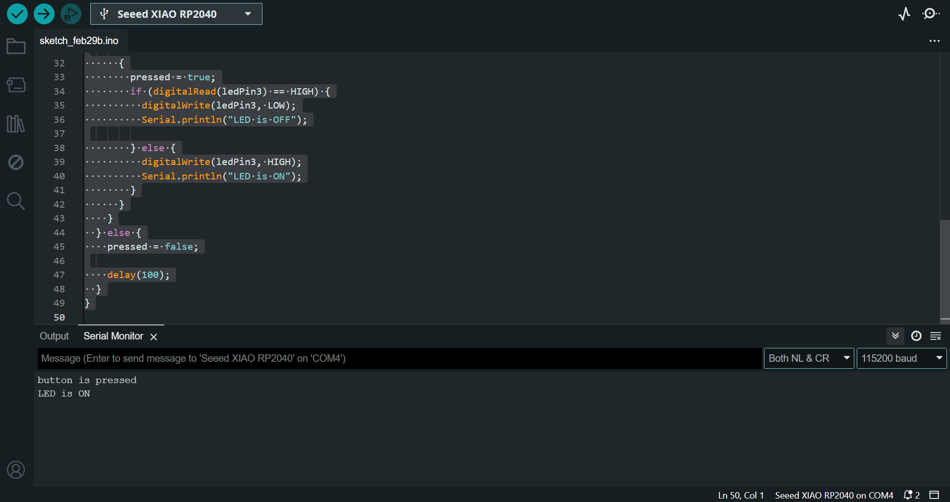
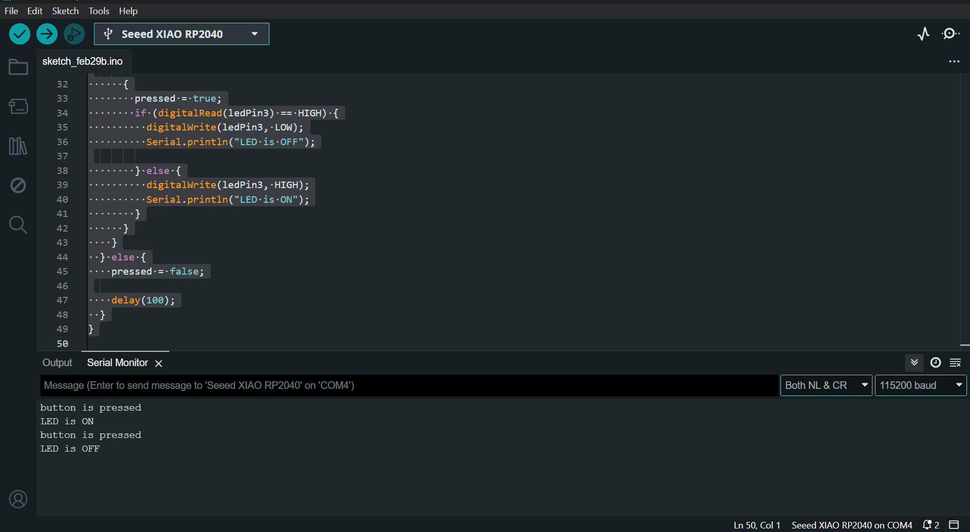
Using this feature, I printed the message to indicate the initialization of the board with the Serial monitor, indicate the status the button is pressed; LED is ON and Button is pressed; LED is OFF using the following code.
// Define the pin numbers
const int buttonPin = 27;
const int ledPin1 = 0;
const int ledPin2 = 1;
const int ledPin3 = 26;
bool ledState = false;  // false means LEDs are OFF, true means LEDs are ON
bool buttonState = false;
bool pressed = false;
void setup() {
  Serial.begin(115200);  // Initialize the button pin as an input with an internal pull-up resistor
  pinMode(buttonPin, INPUT);

  // Initialize the LED pins as outputs
  {
    pinMode(ledPin1, OUTPUT);
    digitalWrite(ledPin1, LOW);
    pinMode(ledPin2, OUTPUT);
    digitalWrite(ledPin1, LOW);
    pinMode(ledPin3, OUTPUT);
    digitalWrite(ledPin3, LOW);  // Make sure LEDs are OFF at the start
  }
  delay(2000);
  Serial.println("LED_CHECK_FAB'24 - KS");
}

void loop() {
  buttonState = digitalRead(buttonPin);
  if (buttonState == HIGH) {
    if (pressed == false) {
      Serial.println("button is pressed");

      {
        pressed = true;
        if (digitalRead(ledPin3) == HIGH) {
          digitalWrite(ledPin3, LOW);
          Serial.println("LED is OFF");

        } else {
          digitalWrite(ledPin3, HIGH);
          Serial.println("LED is ON");
        }
      }
    }
  } else {
    pressed = false;

    delay(100);
  }
}
The output on the Serial Monitor is displayed as follows:
When button is pressed and LED is ON, the output is as follows:
When button is pressed and LED is OFF, the output is as follows:
Our instructor was helping us understand the concept of recursive functions and taught us how to call recursive functions. To try this in our current program, he asked us to write a code to toggle between the three LEDs on pins 26, 0, and 1 each time the button is pressed.
The code is given as follows:
const int buttonPin = 27;
const int ledPins[] = {26, 0, 1};
const int numLeds = sizeof(ledPins) / sizeof(ledPins[0]);
int currentLed = 0; // Index of the currently active LED
bool lastButtonState = HIGH; // Assume button is released initially
void setup() {
pinMode(buttonPin, INPUT_PULLUP); // Button pin set as input with pull-up
for (int i = 0; i < numLeds; i++) {
pinMode(ledPins[i], OUTPUT); // LED pins set as output
digitalWrite(ledPins[i], LOW); // Ensure all LEDs are off initially
}
}
void loop() {
bool currentButtonState = digitalRead(buttonPin);
// Check if button state transitioned from HIGH to LOW (button press)
if (lastButtonState == HIGH && currentButtonState == LOW) {
toggleLed(); // Function to handle LED toggling
// Debounce delay
delay(50);
}
lastButtonState = currentButtonState; // Update the last button state
delay(10); // Small delay to prevent reading too fast
}
void toggleLed() {
// Turn off the current LED
digitalWrite(ledPins[currentLed], LOW);
// Move to the next LED, wrapping around if necessary
currentLed = (currentLed + 1) % numLeds;
// Turn on the next LED
digitalWrite(ledPins[currentLed], HIGH);
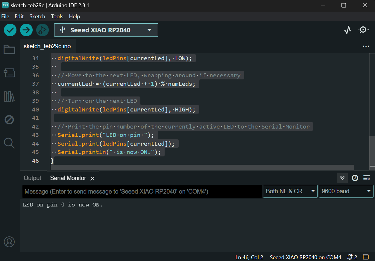
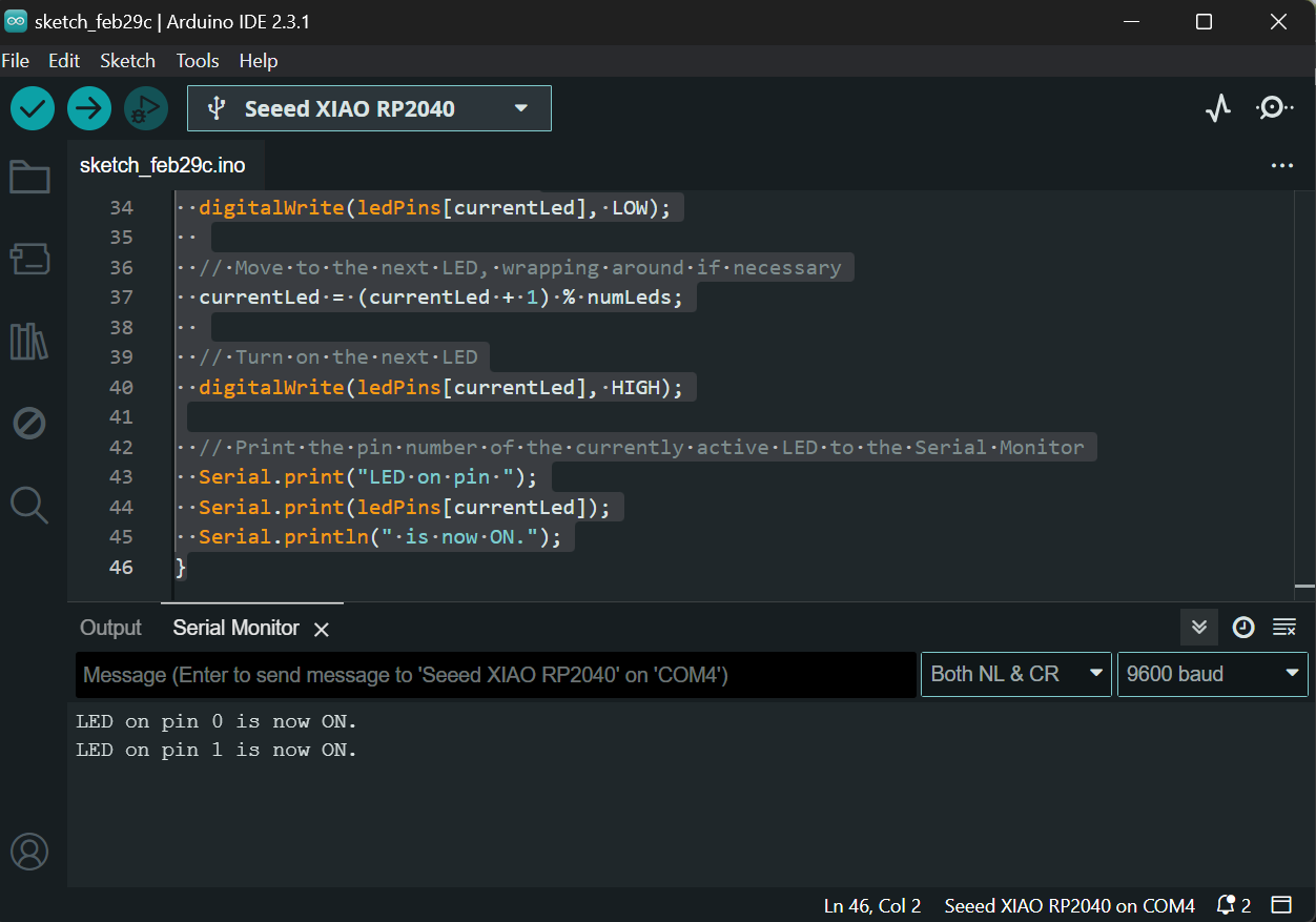
}Furthermore, I tried to integrate the serial monitor output to the previous program and indicate the pin number of the LED that is ON. The code is as follows:
const int buttonPin = 27;
const int ledPins[] = {26, 0, 1};
const int numLeds = sizeof(ledPins) / sizeof(ledPins[0]);
int currentLed = 0; // Index of the currently active LED
bool lastButtonState = HIGH; // Assume button is released initially
void setup() {
Serial.begin(9600); // Initialize serial communication at 9600 baud rate
pinMode(buttonPin, INPUT_PULLUP); // Button pin set as input with pull-up
for (int i = 0; i < numLeds; i++) {
pinMode(ledPins[i], OUTPUT); // LED pins set as output
digitalWrite(ledPins[i], LOW); // Ensure all LEDs are off initially
}
}
void loop() {
bool currentButtonState = digitalRead(buttonPin);
// Check if button state transitioned from HIGH to LOW (button press)
if (lastButtonState == HIGH && currentButtonState == LOW) {
toggleLed(); // Function to handle LED toggling
// Debounce delay
delay(50);
}
lastButtonState = currentButtonState; // Update the last button state
delay(10); // Small delay to prevent reading too fast
}
void toggleLed() {
// Turn off the current LED
digitalWrite(ledPins[currentLed], LOW);
// Move to the next LED, wrapping around if necessary
currentLed = (currentLed + 1) % numLeds;
// Turn on the next LED
digitalWrite(ledPins[currentLed], HIGH);
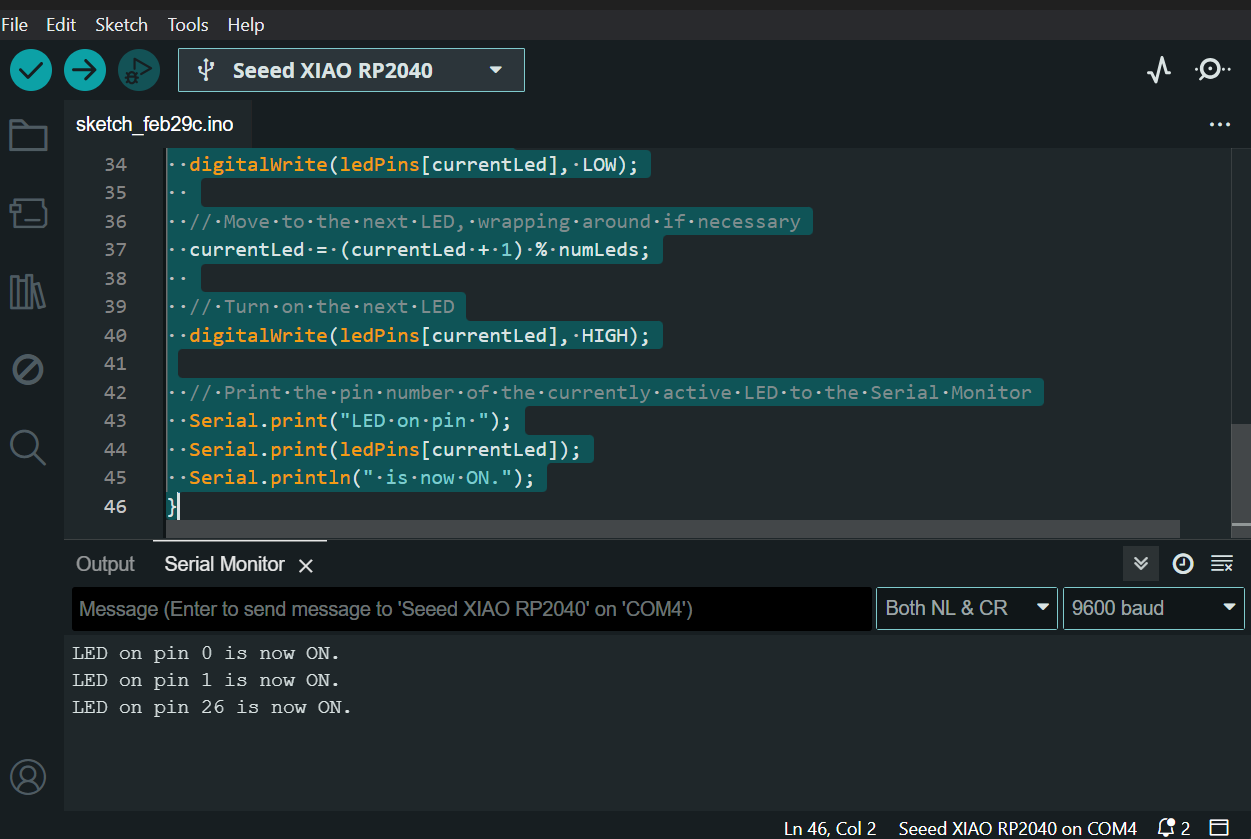
// Print the pin number of the currently active LED to the Serial Monitor
Serial.print("LED on pin ");
Serial.print(ledPins[currentLed]);
Serial.println(" is now ON.");
}The output of the serial monitor when LED on pin 0 glows on pressing the button is as follows:
The output of the serial monitor when LED on pin 1 glows on pressing the button is as follows:
The output of the serial monitor when LED on pin 26 glows on pressing the button is as follows:
For extra credits, I was trying a different environment of Micropython using Thonny editor. I installed the Thonny editor using the steps mentioned in the following documentation .
I installed Thonny Editor 3.10 for Windows 64 Bit from the following site:
I installed it using the setup wizard and the interface displayed as follows:
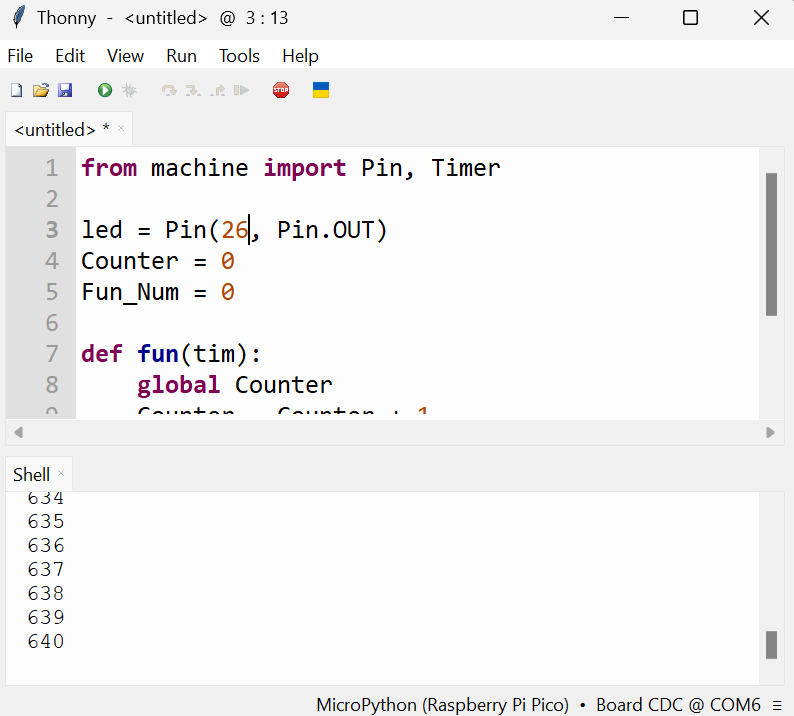
As shown above, our instructor helped me test a sample counter program and I noticed the difference between Micropython and Arduino. My instructor mentioned that’s because the former is an interpreter and the latter is a compiler.
A compiler and an interpreter both translate source code written in a high-level programming language to machine code that a computer can execute. However, they do this in different ways:
- A compiler translates the entire program into machine code before it is executed. This process generates an executable file that can be run independently of the original source code.
- An interpreter, on the other hand, translates and executes the source code line by line while the program is running. It does not create an executable file.
Because of these differences, compiled programs generally run faster than interpreted ones. However, interpreted languages can provide more flexibility and ease of development, as they allow for dynamic typing, interactive use, and the ability to execute code on the fly.
Here’s the code on Micropython for blinking LED on pin 26.
from machine import Pin
import time
Initialize GPIO 1 as an output pin for the LED
led = Pin(26, Pin.OUT)
while True:
led.value(1) # Turn the LED on (HIGH is the voltage level)
time.sleep(1) # Wait for a second
led.value(0) # Turn the LED off
time.sleep(1) # Wait for a second
print("LED 26 is blinking")